
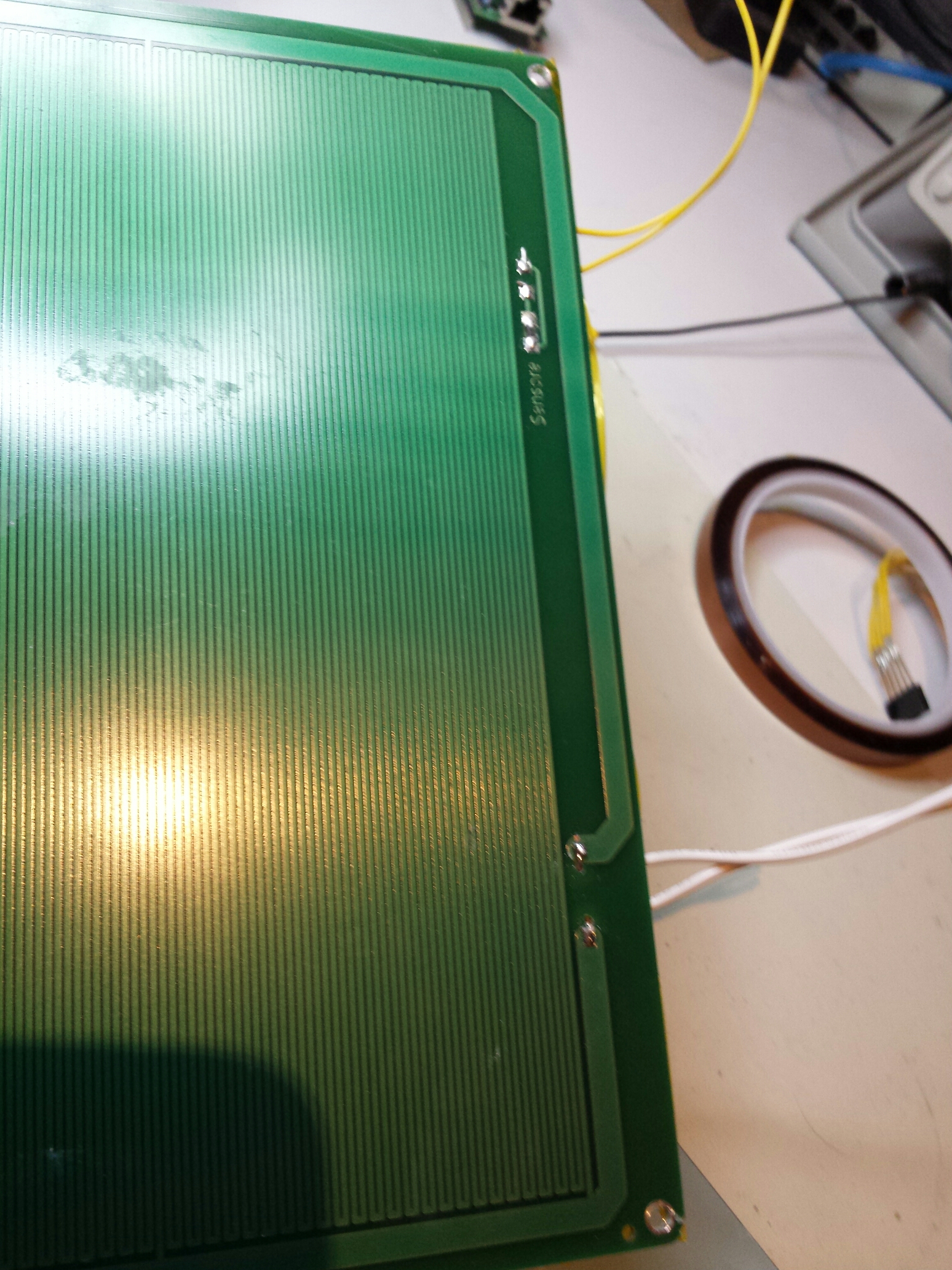
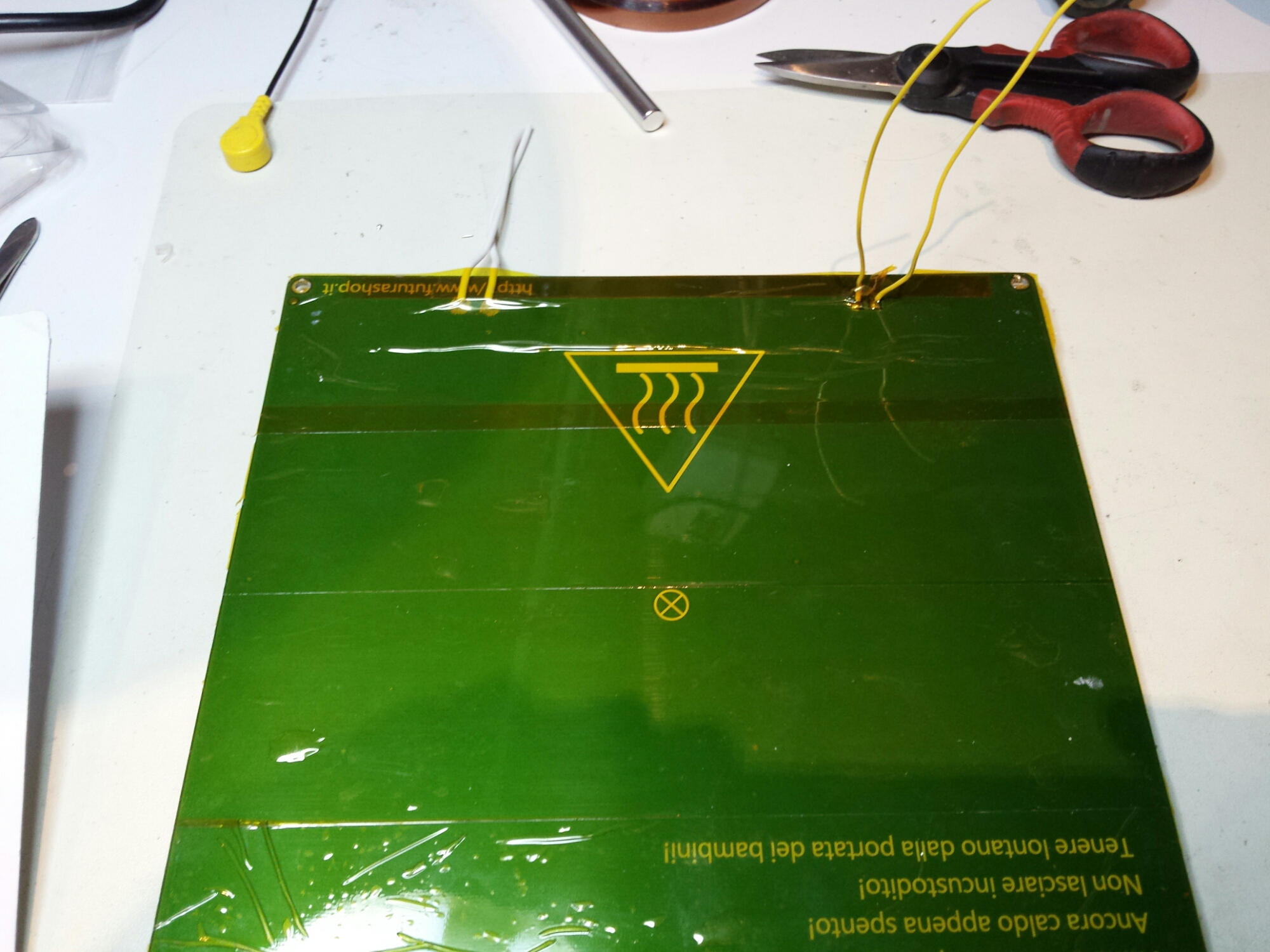
For ABS and other polymers i need a better hotbed than the one shipped by default with my 3drag. Basically i need a better leveled surface and a more hot plate. So, my solution is to buy the 90 degree declared standard hotbed for 3drag and modify it to reach up to 150 degree, and add a mirror on top of that.
First, i will reverse upside down the hotbed to get the hotter part of the hotbed attached directly to the downside of the mirror. To do that i need to modify it with my dremel tool a little bit, and then to use my dremel on the downside of the mirror too.
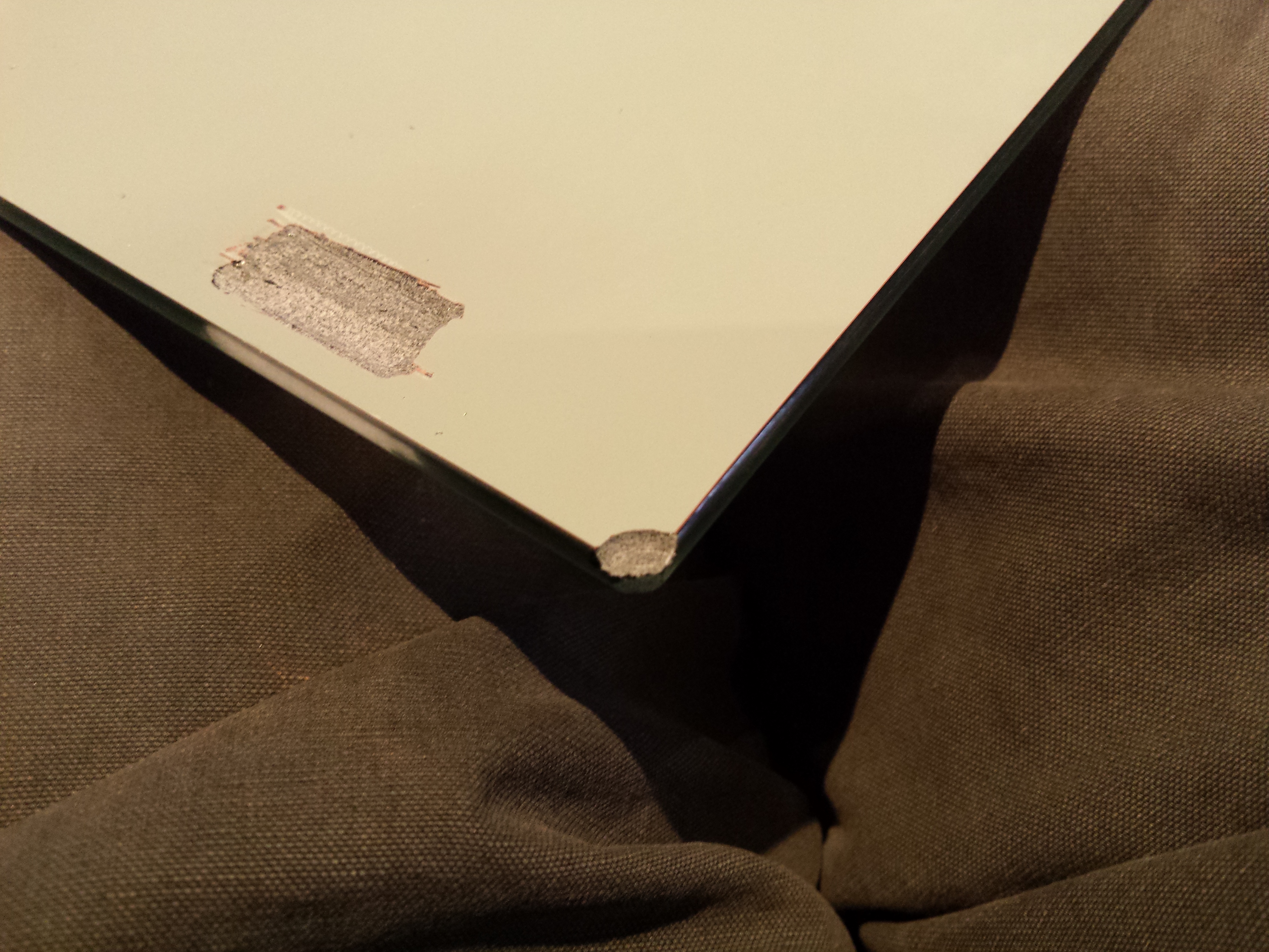
(…when you work on glass/mirrors, this is how your tool will be when you finish: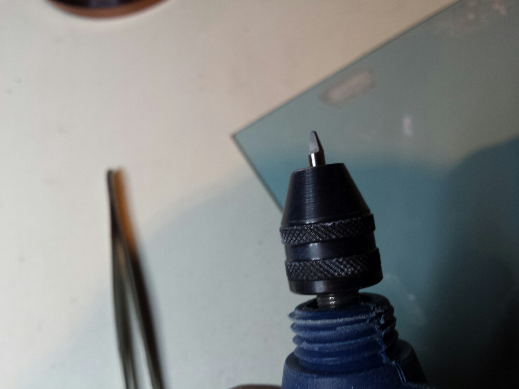 )
)
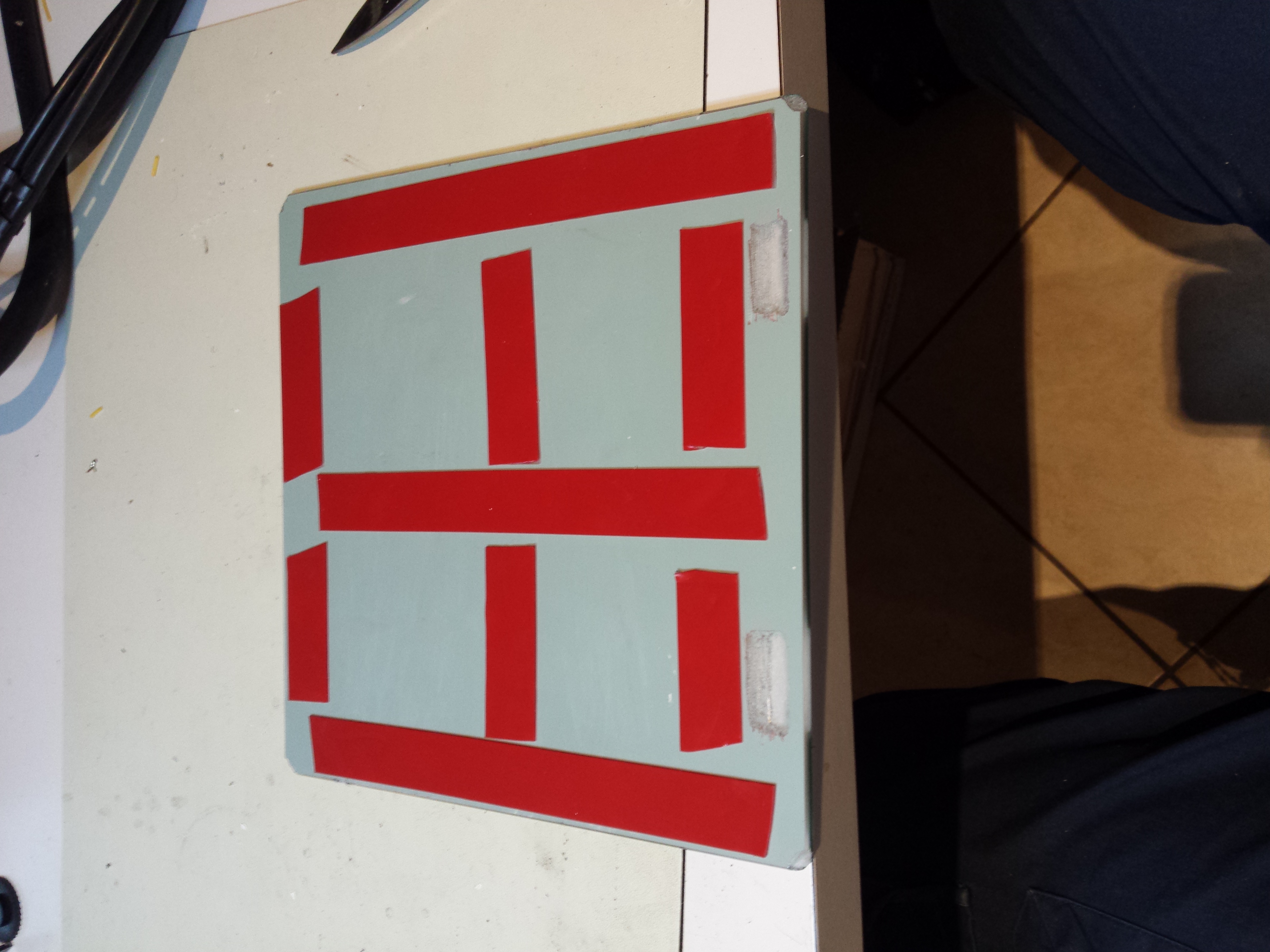
To better thermal isolation a layer of kapton tape is added on the “now downside” of the hotbed PCB
Also, the standard thermal isolation is added
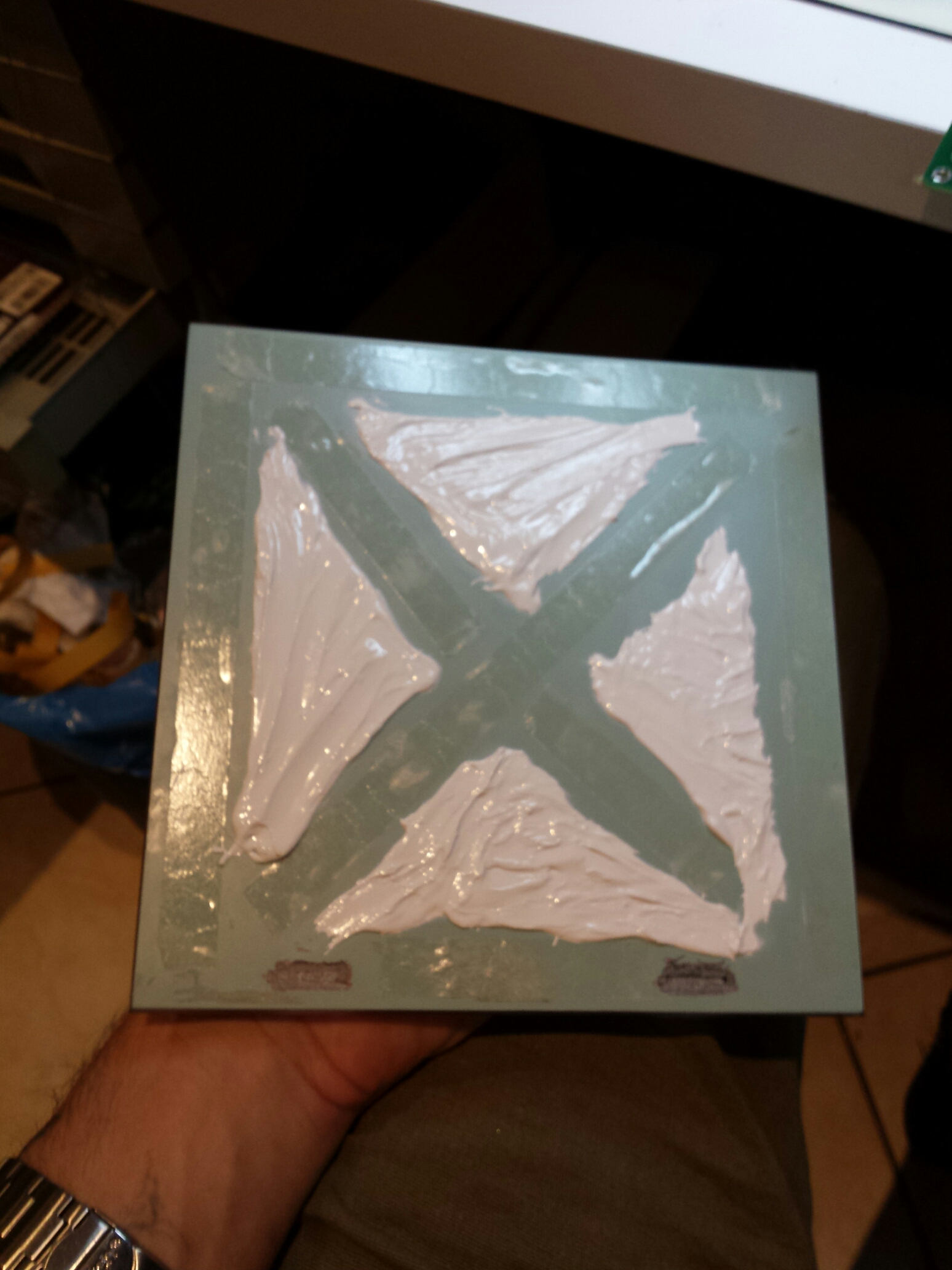
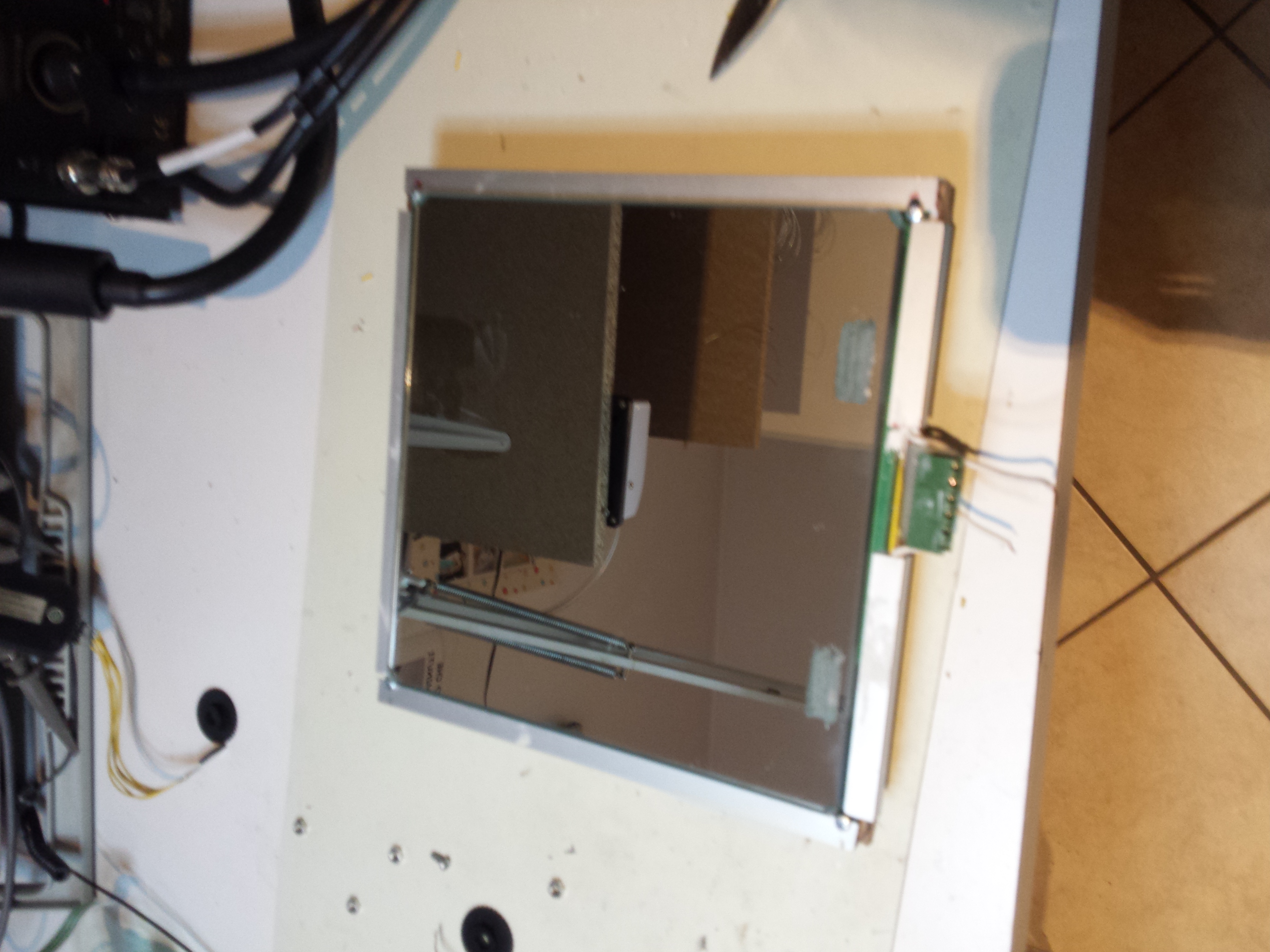
then, some double side tape and thermal paste on the downside of the mirror
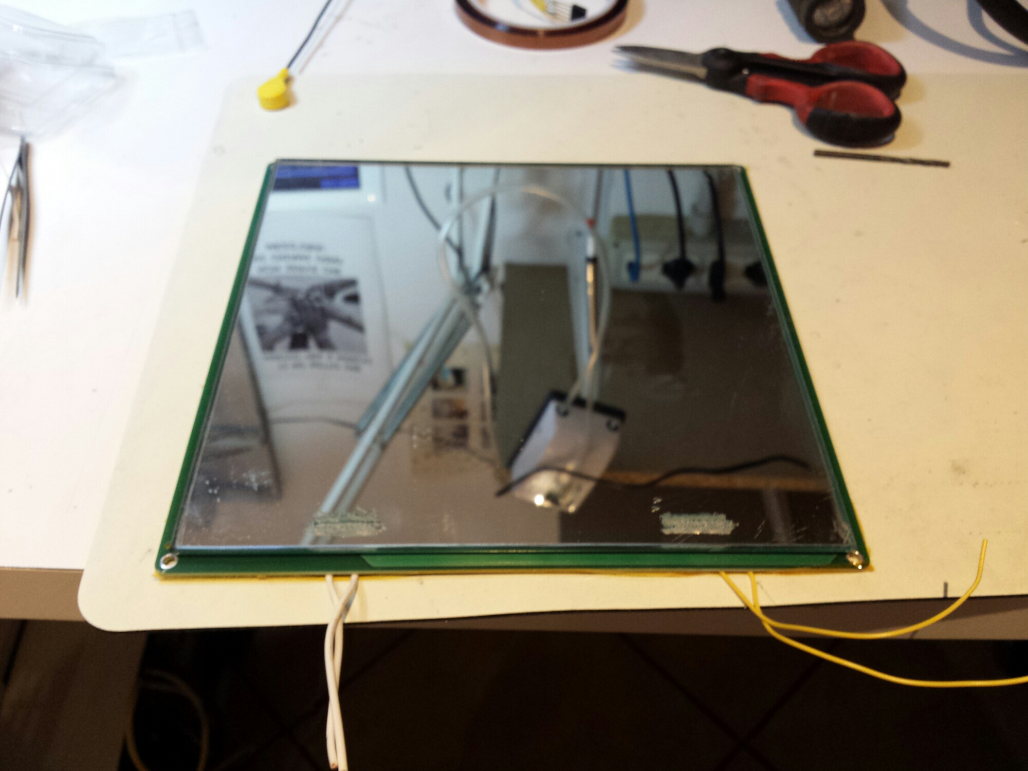
and the mirror is attached on top of the PCB
after some tests, some issues raised:
- the double side tape mold at ~ 85 degree, making the mirror moving
- too heat is disperded on the metal mount
- the termistor is in a bad position: as PCB vetronite isn’t a great heat conductor, it measure only 50 degree when the plate is 90 degree
- the screw are too close to the mirror borders, making it don’t adhere perfectly to the PCB
So, i’m going in a new and better try.
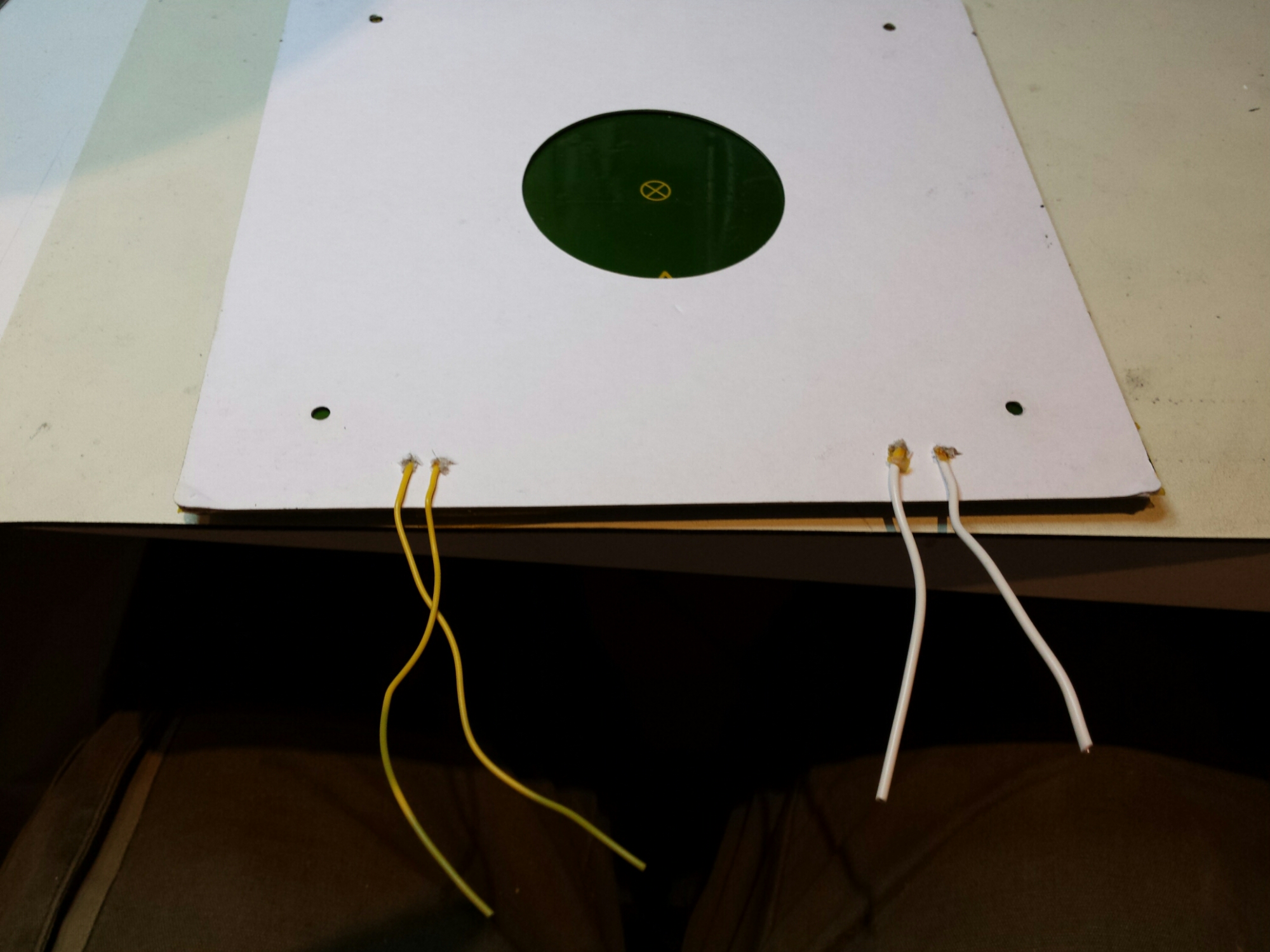
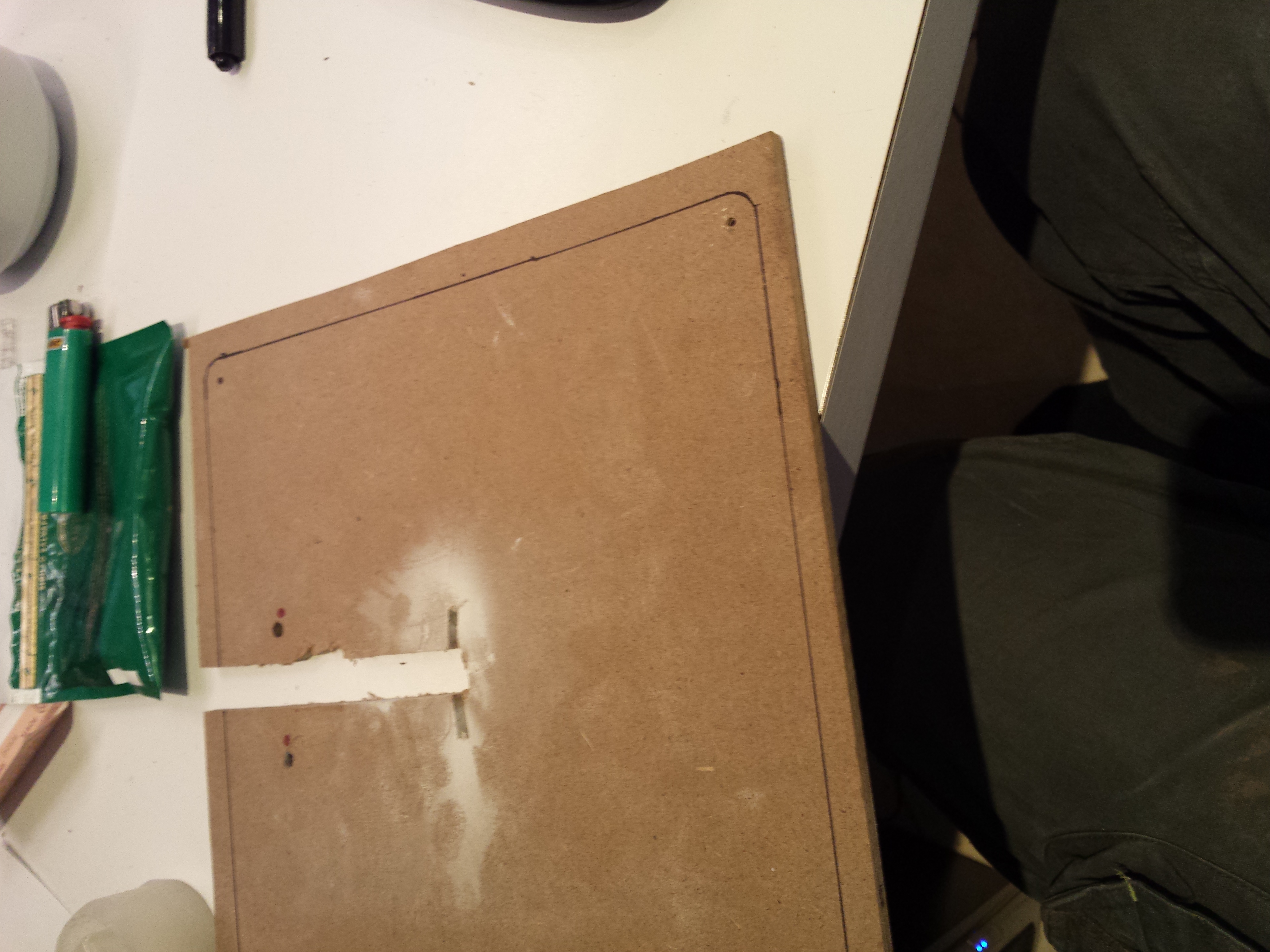
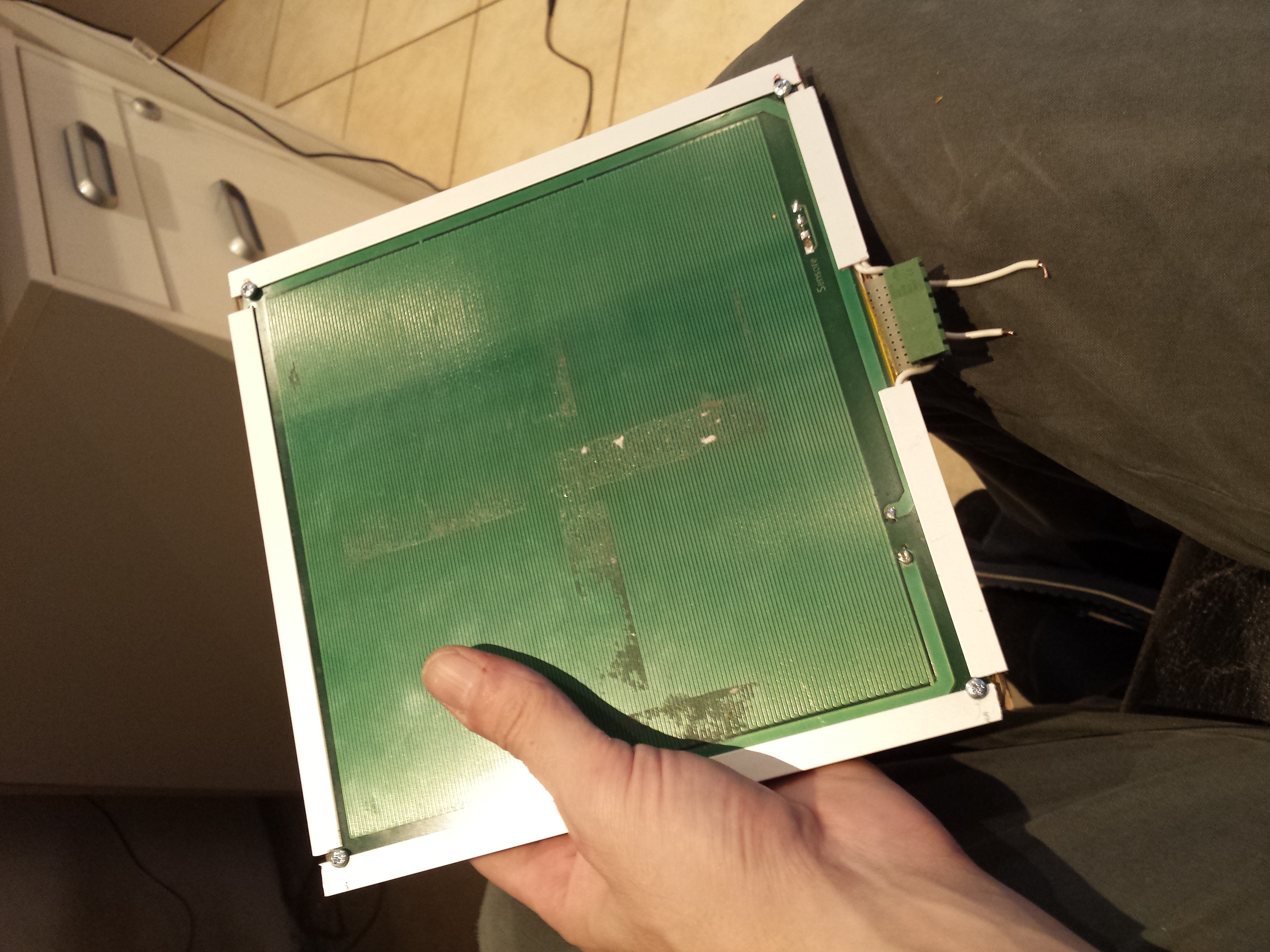
First of all, i moved the termistor to the center of the now downside of the bed, building two traces with my dremel on the copper plated surface.
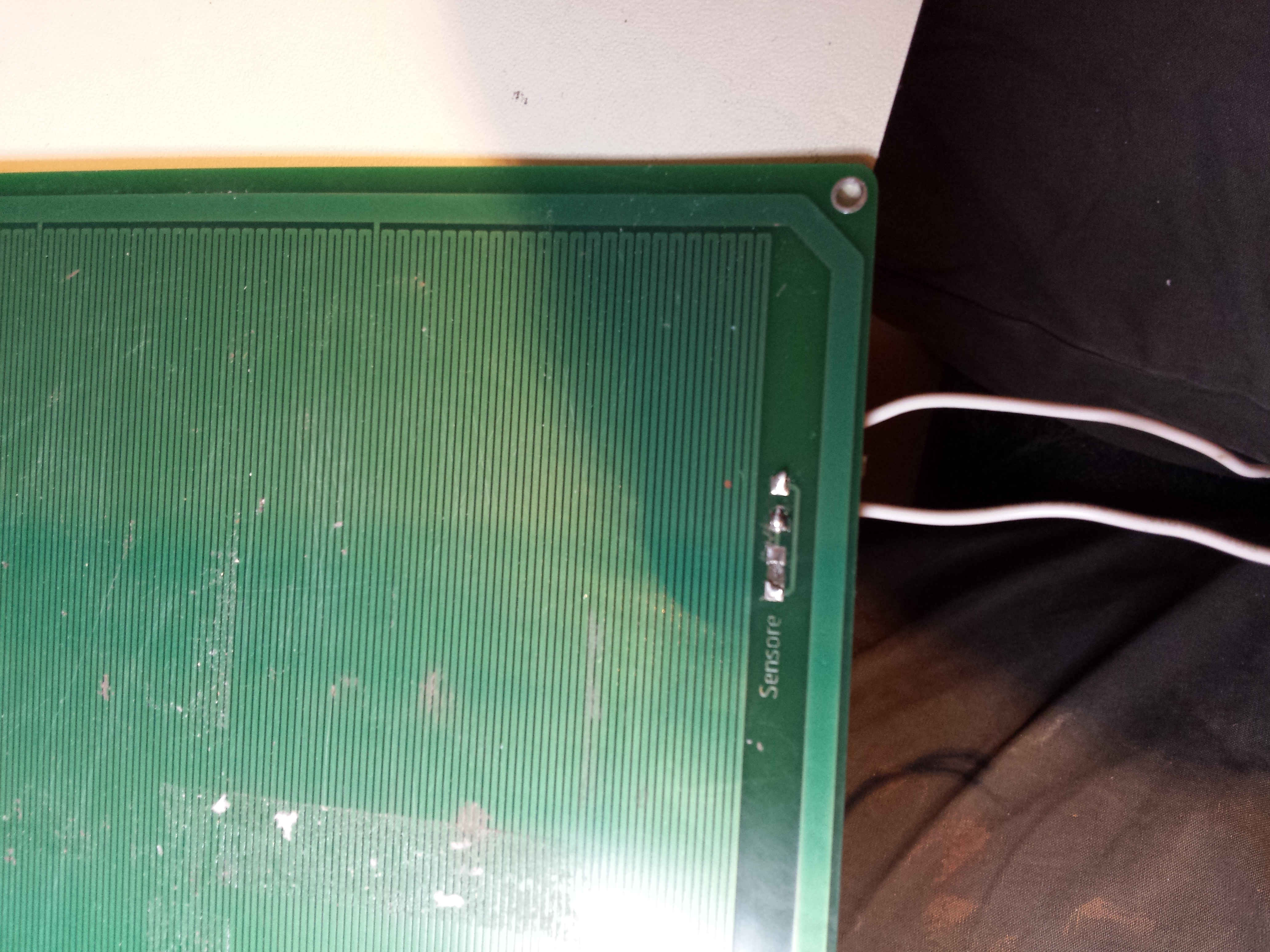
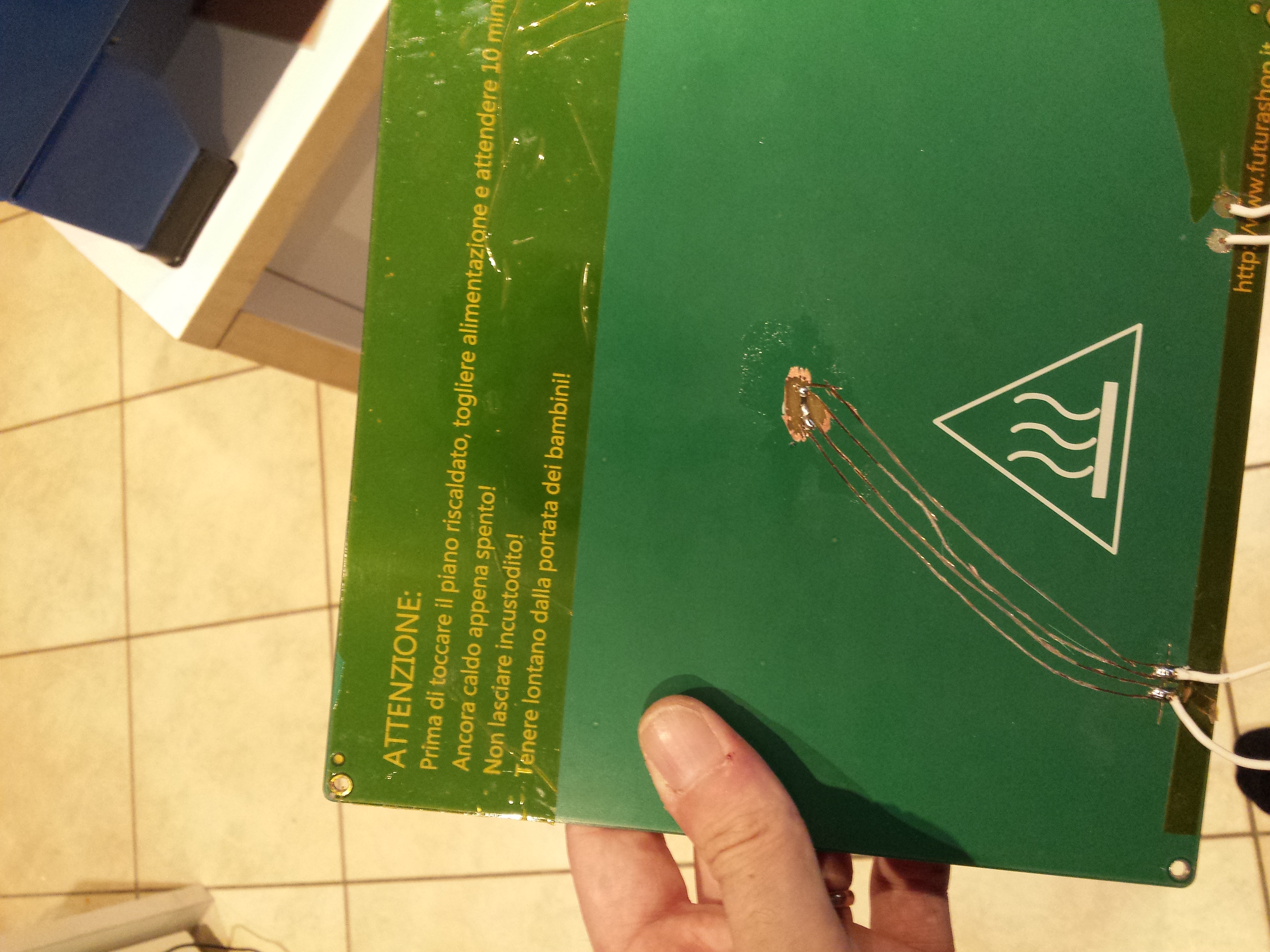
carefully soldering the termistor inside a little hole at the center of the plate with a large insulating zone.
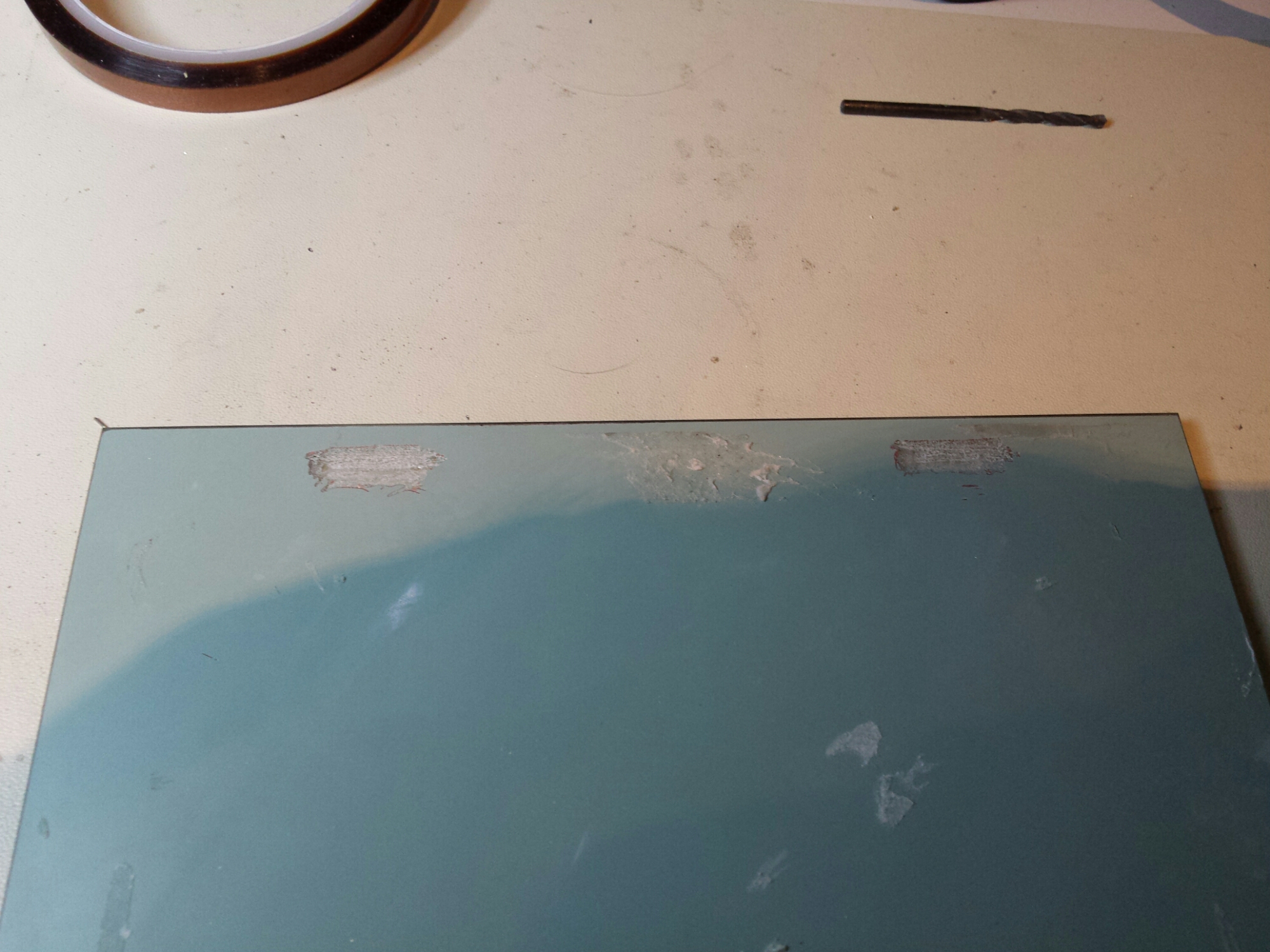
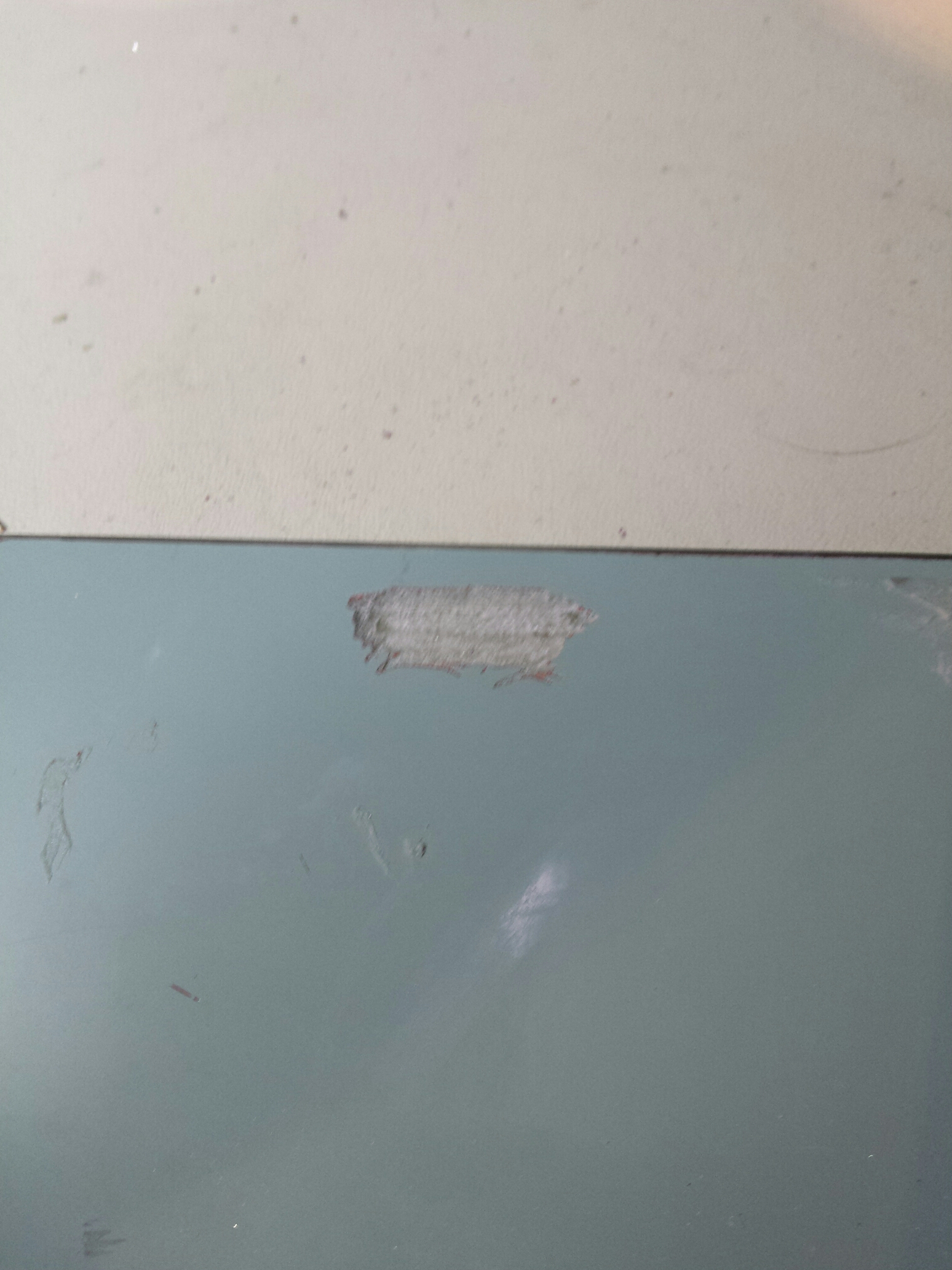
To get better adherence with the mirror, i very carefully milled mirror borders where screws are on the PCB:
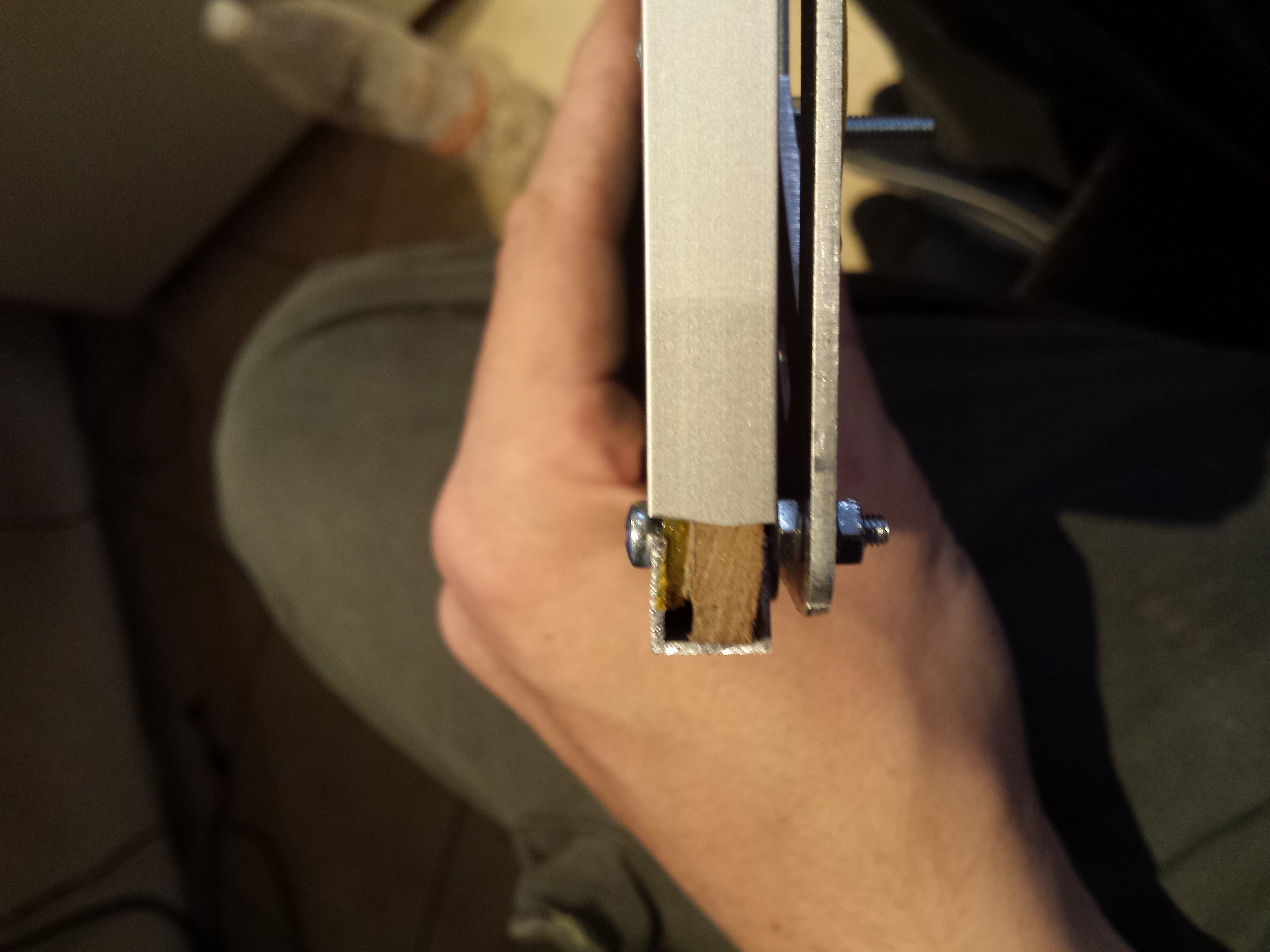
Next issue to solve is to get a better thermal isolation on the downside of the heatbed, so, i’ve added a plywood layer: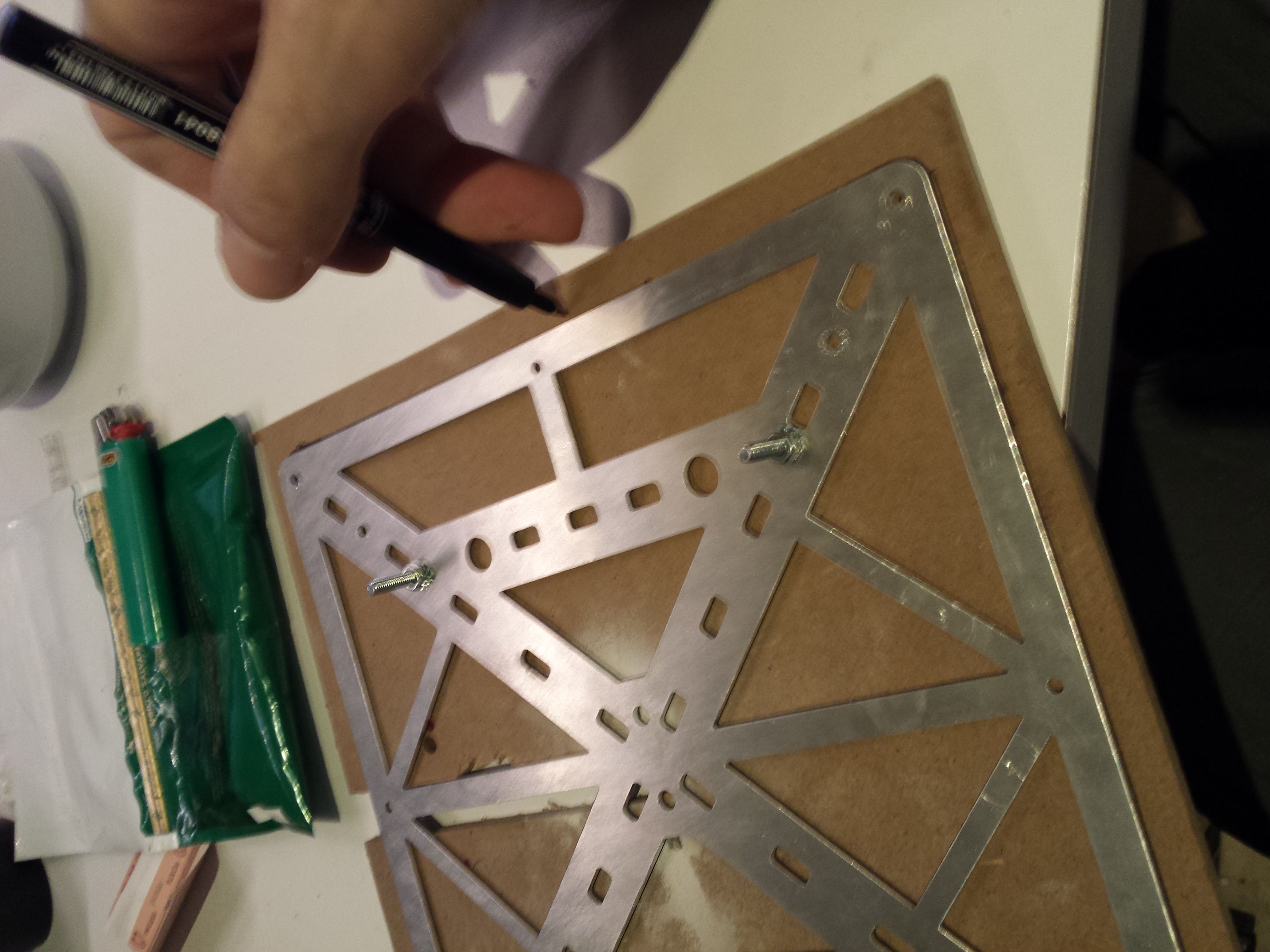
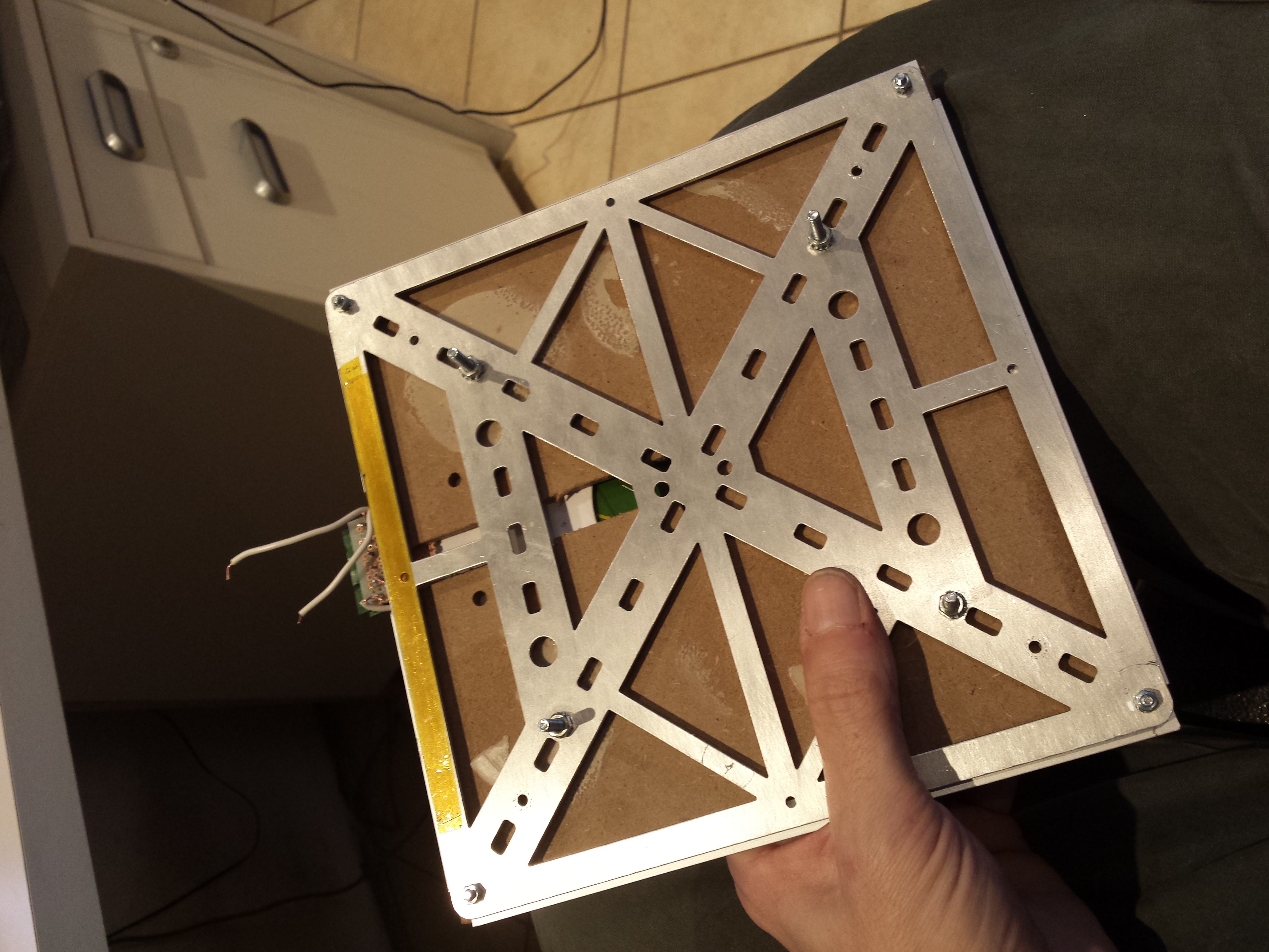
and fixed it with some aluminium profiles and screws
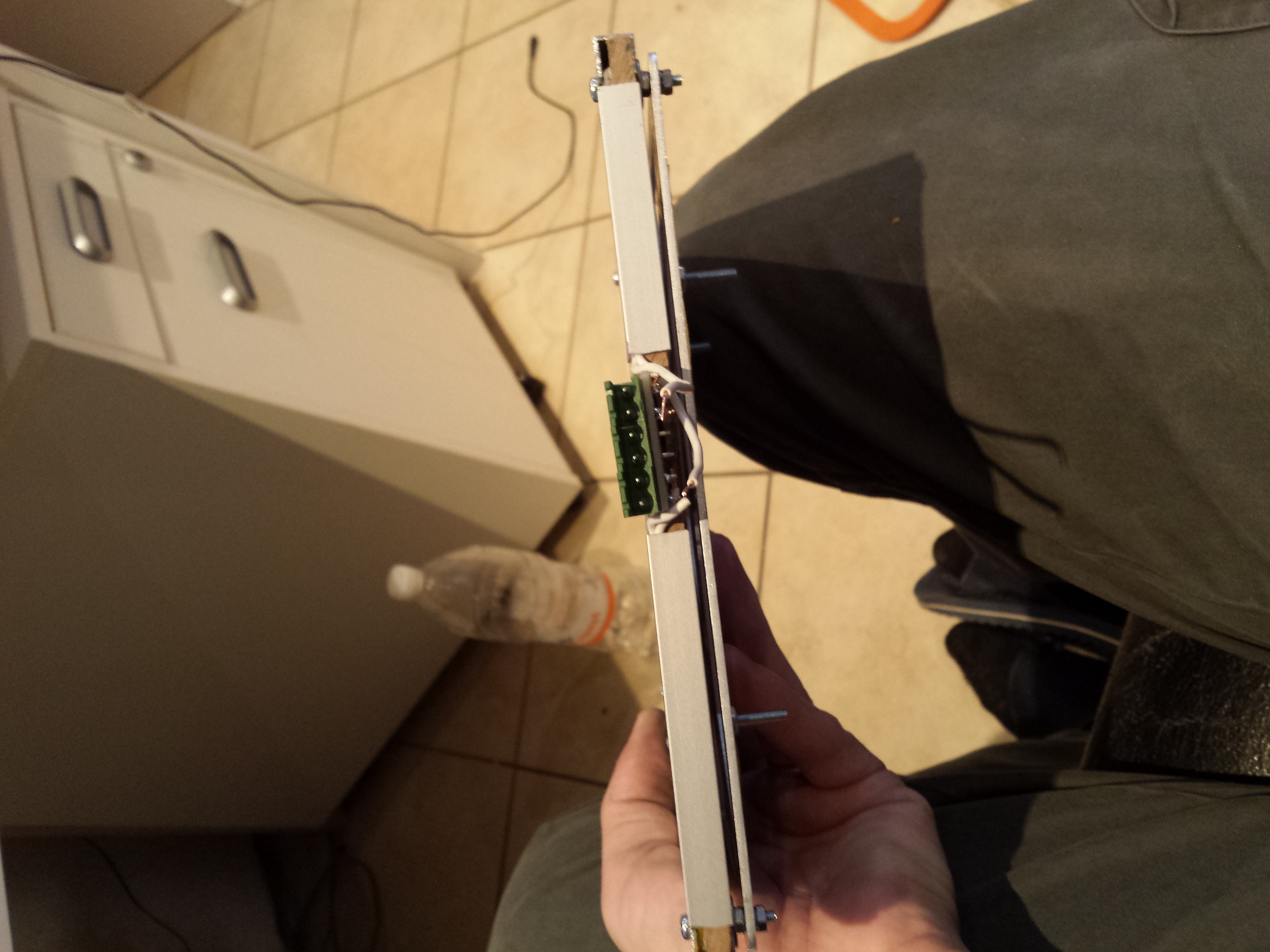
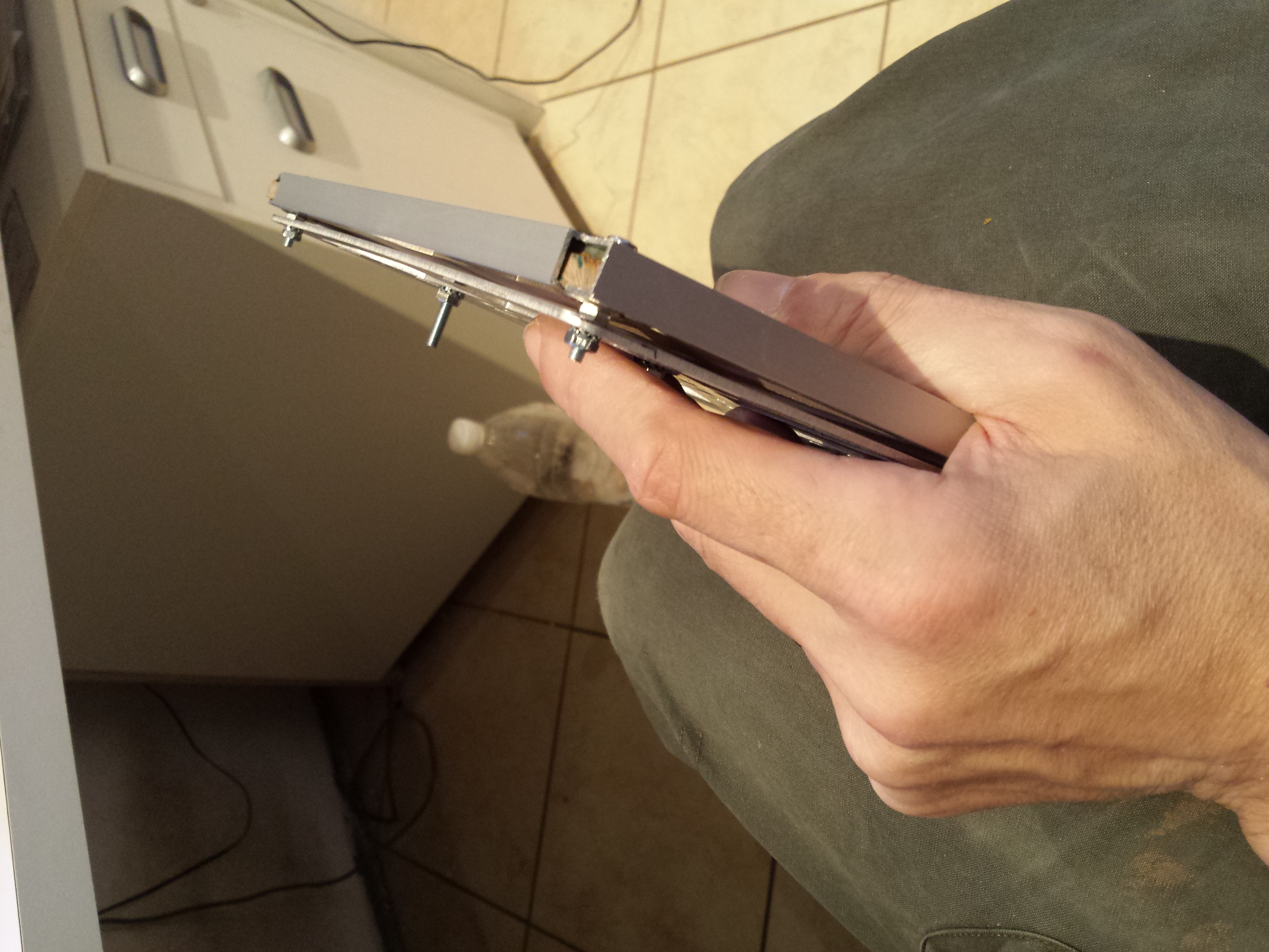
then, using an high temperature (up to 180 degree) double side tape, fixed the mirror on top:
Let’s go testing: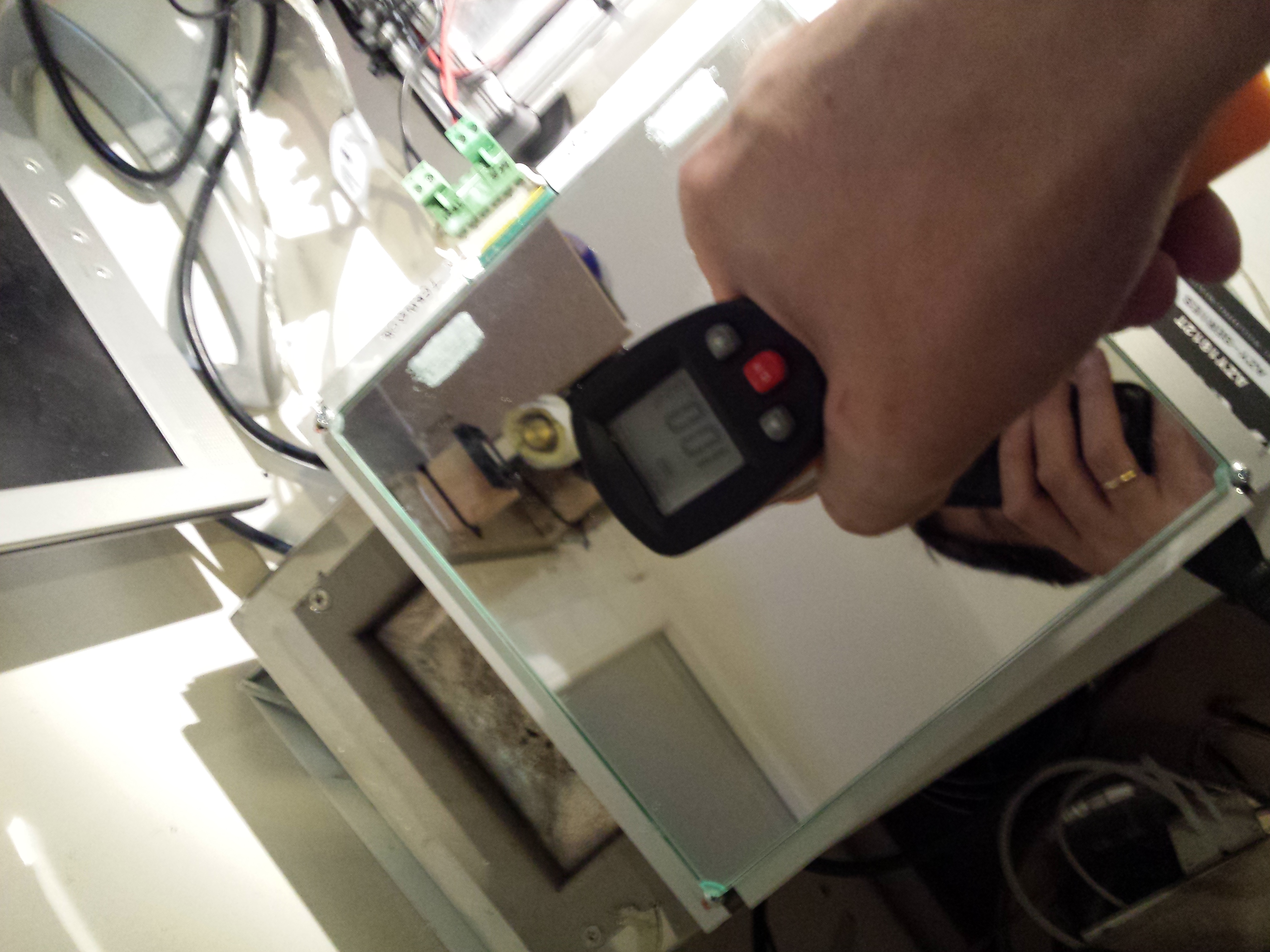
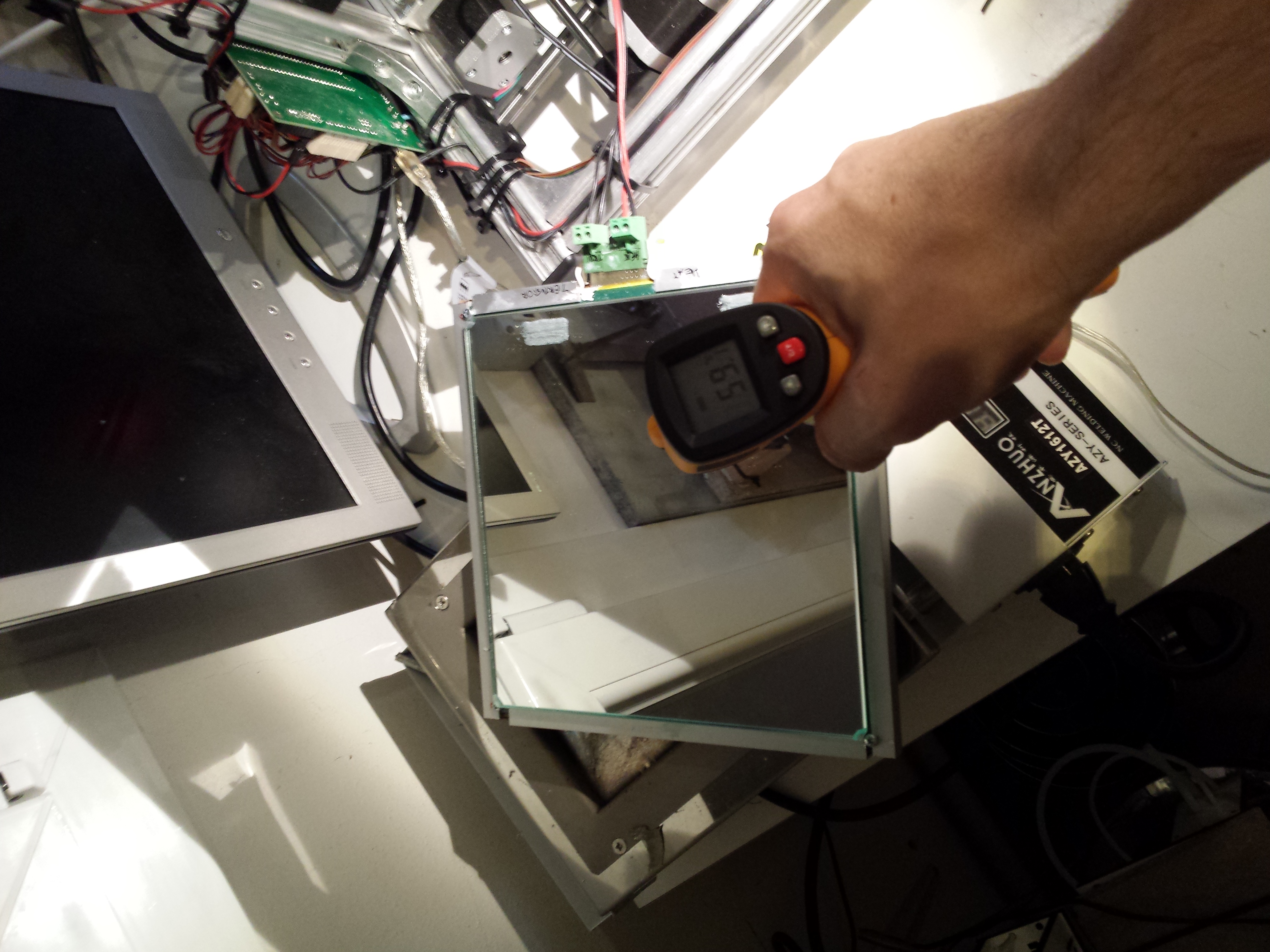
with 15V 150W power supply on the original board i can get up to 100 degree in 5 minutes. Let’s mount it on the printer.
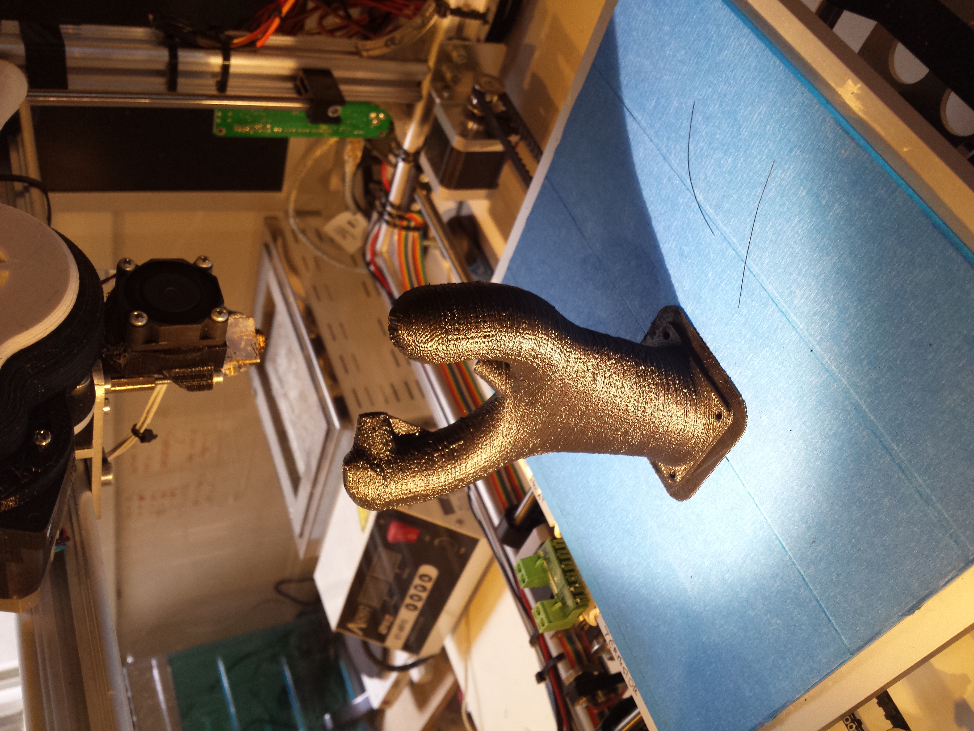
After a first print test with hotbed at 80 degree, next step will be the 24V modification…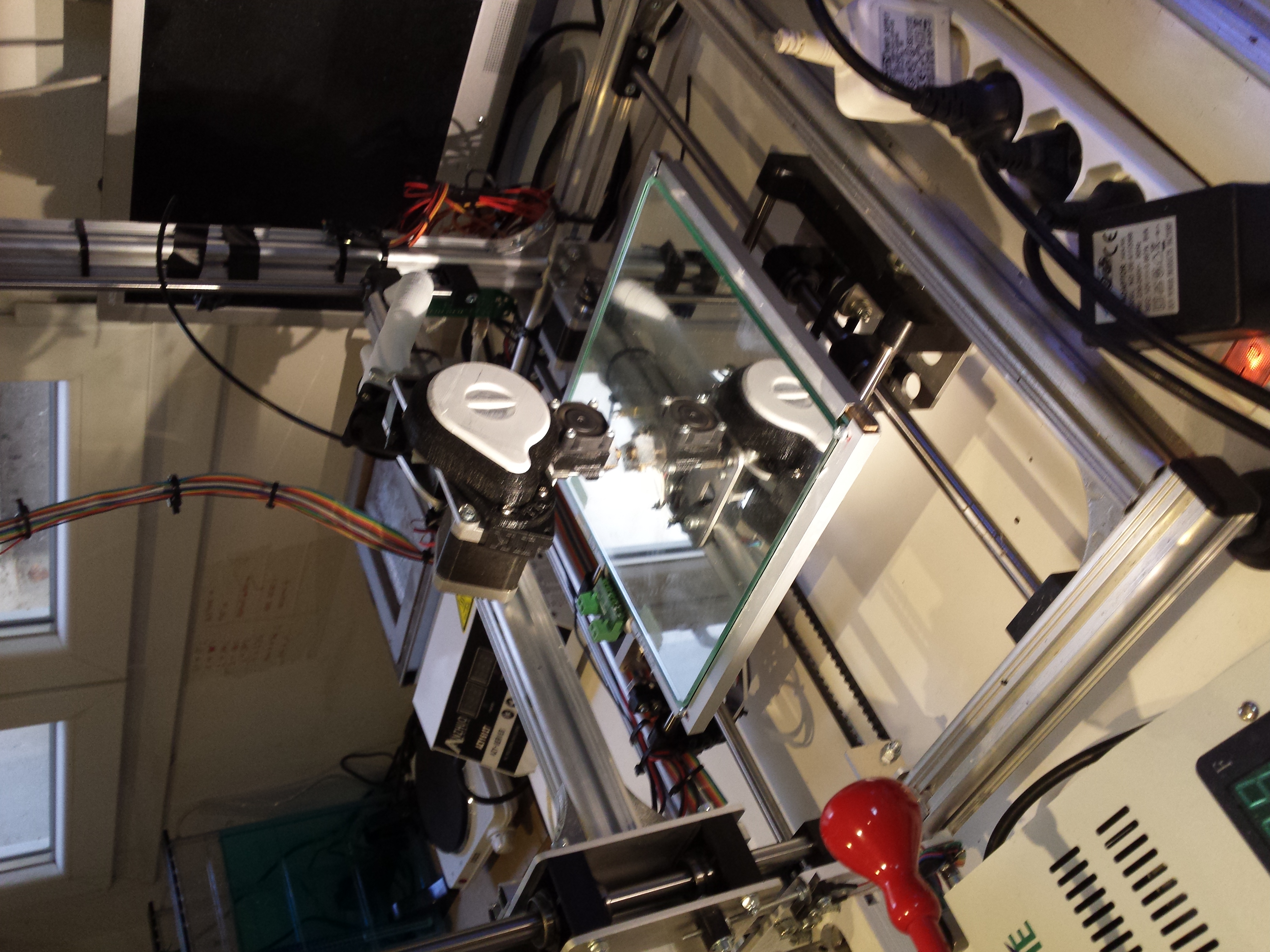

23 March 2015 at 01:00
Great write up. Do you have a link to the power supply you used for this setup?
23 March 2015 at 13:45
I’ve used a common 24V switching power supply, with a little circuit to drive the plate. I will post schematics and all on my github ( and also here ) next month when i will be back at home :)