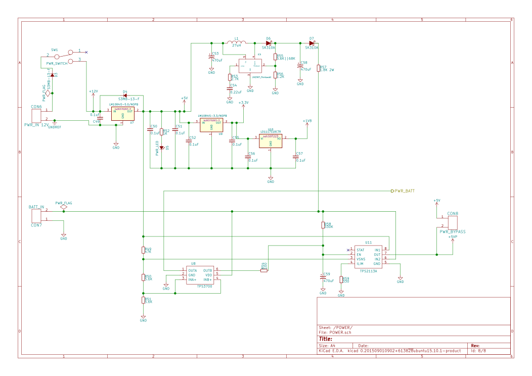
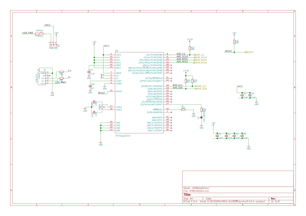
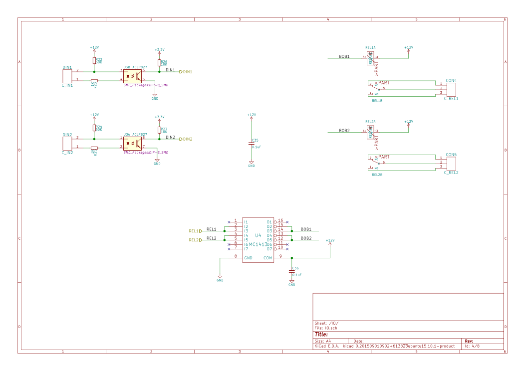
Rasky schematic is almost complete, only the power supply stage and few other things like some leds and some capacitors remain to add, and then will be time to place components and route traces on the PCB.
Few things about the schematic:
- The logic for the CPLD/FPGA is fairly simple, so, we can use a CPLD instead of an FPGA, but the initially chosen MaxII epm240 isn’t enough, so, I replaced it with a MaxII epm570. It adds ~5€ to the total cost of components, but i can absorb this cost without rebate it to the users.
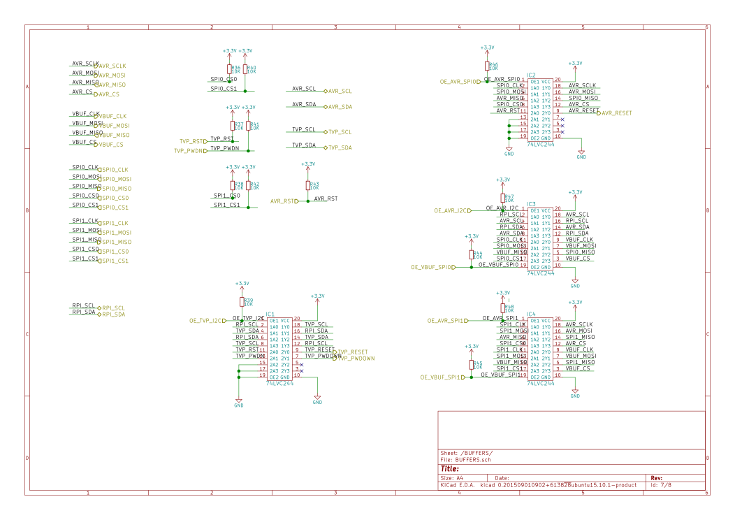
- I’m protecting and driving all SPI and I2C connections with a signal buffer, this way i can switch on/off connections and avoid to burn the raspberry pi pins, and power the atmega at 5V other than programming it from the raspberry itself
- The raspberry pi 2B has another SPI exposed on the P1 header, thanks to the signal buffer ICs i will try to use it by let which device attach to which SPI on the Raspberry via software on the raspberry itself.
Please, take care that this is a work in progress, it’s not yet complete at 100% nor well tested/checked, don’t use it (yet) for anything except to evaluate Rasky progresses!
- Direct link to the PDF schematic: https://git.nexlab.net/rasky/Rasky_hw/raw/master/Rasky_v1.pdf
- Rasky HW gitlab repository with kicad project: https://git.nexlab.net/rasky/Rasky_hw
Please, don’t discard to share and evangelize the Rasky crowdfunding campaign: https://www.nexlab.net/product/rasky


Leave a Reply
You must be logged in to post a comment.